Cat 6 Poe Camera Wiring Diagram - How To Wire A Cctv Camera And System. Green & white pin 4: Ip needs 2 pairs of wire to communicate with the nvr. Orange & white pin 2: Below is a description of the basic functionality of each wire associated with the ethernet port pins these cameras: Cat 5/cat 6 poe cameras are first plugged into a poe switch/poe injector or network video recorder (nvr) with poe ports and a network router, and then the security camera will be up and running.
Brown & white pin 8: Otherwise, the arrangement won't function as it ought to be. Orange & white pin 2: Currently, 2 types of wiring are widely used for ip security cameras which are cat6 or cat5e twisted pair cabling. Reliable network with ethernet cat6 wiring.
Poe Cat5e Wiring Diagram Vtg 3000le Boiler Wiring Diagram 7gen Nissaan Ke2x Jeanjaures37 Fr from 2.8.2.3.4.4.2.6.9.dba.skylink.hr Category 5 / 5e & cat 6 cabling tutorial and faq's. Hikvision ip camera rj45 pin out wiring diagram cornick poe details cruze cctv injectors cameras installation and options network repair the cable on a simplified ethernet online how to wire learn com cat 5 crossover power over switch faqs lorex works kintronics connect nvr surveillance security types 12 volt. A very common question regarding security cameras and installs is the type of cabling to use. Ip needs 2 pairs of wire to communicate with the nvr. 06:58 2 comments one cannot imagine living without networks in the present times. In most cases you run your video and power to and from the camera on the same cat5 or cat6 wire, assuming you are using a poe (power over ethernet) power source such as a poe injector or poe switch. Otherwise, the arrangement won't function as it ought to be. I of course know what the standard rj45 a and b type pinouts are but the problem is, when you open up the camera or strip some of the outer jacket from the cable, amcrest is not using standard colors for the wires to the rj45.
You may follow the wire order below to arrange the wires of your rj45 connector.
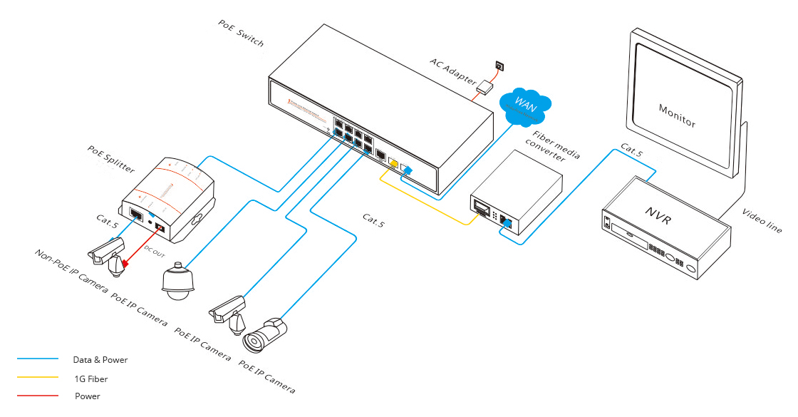
As external power doesn't needed in poe ip cameras, therefore connect only the cameras through poe via cat5 / cat 6 cables. Category 5 / 5e & cat 6 cabling tutorial and faq's. Below is a description of the basic functionality of each wire associated with the ethernet port pins on your camera: Cat 5/cat 6 poe cameras are first plugged into a poe switch/poe injector or network video recorder (nvr) with poe ports and a network router, and then the security camera will be up and running. In most cases you run your video and power to and from the camera on the same cat5 or cat6 wire, assuming you are using a poe (power over ethernet) power source such as a poe injector or poe switch. I plan to use 2 cameras on the cat6 cable without any adapters or switch. Currently, 2 types of wiring are widely used for ip security cameras which are cat6 or cat5e twisted pair cabling. To get a better idea, the ethernet ip security camera wiring diagram is shown below. You can use passive poe splitter and poe injector and the wire length can be 130 feet (40 meter). I need to install new sockets but don't know the wiring diagram. If you do decide to go the cat6 route there will be a few more options. Your cat 6 wiring diagram for poe ought to have lines and shapes representing power and ground. Power over ethernet wiring diagram category 5 cable ip camera png 800x484px area.
Poe outdoor cam rj45 cable pinouts. Cat 6 poe camera wiring diagram / to get a better idea, the ethernet ip security camera wiring diagram is shown below. If you do decide to go the cat6 route there will be a few more options. Otherwise, the arrangement won't function as it ought to be. Reliable network with ethernet cat6 wiring.
Diagram Pelco Security Camera Wiring Diagram For Full Version Hd Quality Diagram For Archerydiagram Cefalubb It from wholefoodsonabudget.com It consists of directions and diagrams for different varieties of wiring strategies as well as other products like lights, windows, and so on. Pins 2 and 3 transmit data to and from the camera. According to earlier, the lines in a cat5 poe wiring diagram represents wires. Blue & white pin 6: Cat 6 poe camera wiring diagram / to get a better idea, the ethernet ip security camera wiring diagram is shown below. Orange & white pin 2: As external power doesn't needed in poe ip cameras, therefore connect only the cameras through poe via cat5 / cat 6 cables. 06:58 2 comments one cannot imagine living without networks in the present times.
Cat 6 poe camera wiring diagram / to get a better idea, the ethernet ip security camera wiring diagram is shown below.
Ethernet rj45 connection wiring and cable pinout diagram pinouts ru from pinouts.ru. 8 pin rj45 8p8c male connector at the cable. Your cat 6 wiring diagram for poe ought to have lines and shapes representing power and ground. Cat5e poe wiring diagram : Cat5 enhanced(cat5e) replaced the traditional cat5 cable and introduced speeds up to ten times faster than cat5 cable. Cat 6 poe camera wiring diagram : You may follow the wire order below to arrange the wires of your rj45 connector. In most cases you run your video and power to and from the camera on the same cat5 or cat6 wire, assuming you are using a poe (power over ethernet) power source such as a poe injector or poe switch. Cat 6 poe camera wiring diagram / dahua ip camera color code pinout for the ethernet ip megapixel cameras and software solutions cctvforum com. 06:58 2 comments one cannot imagine living without networks in the present times. This is what worked for me. Pins 1 and 6 are power, pin 1 is negative and pin 6 is positive. If you do decide to go the cat6 route there will be a few more options.
Currently, 2 types of wiring are widely used for ip security cameras which are cat6 or cat5e twisted pair cabling. To properly read a wiring diagram, one offers to learn how typically the components in the program cat6 poe wiring diagram source: There are a number of different type of power wiring readily. Blue & white pin 6: Wiring diagram also offers helpful recommendations for projects which may require some extra tools.
Poe Connection Poe Switch And A Computer from www.fiber-optic-tutorial.com It consists of directions and diagrams for different varieties of wiring strategies as well as other products like lights, windows, and so on. Each component ought to be placed and connected with different parts in particular way. Here is my understanding of ip cameras and cat5: Below is a description of the basic functionality of each wire associated with the ethernet port pins on your camera: To get a better idea, the ethernet ip security camera wiring diagram is shown below. The camera uses one pair to talk to the nvr wire #1 and #2. Wiring diagram also offers helpful recommendations for projects which may require some extra tools. Otherwise, the arrangement will not function as it should be.
I have two lorex ip cameras (model # mcnb3143) with damaged cat5e sockets.
I have two lorex ip cameras (model # mcnb3143) with damaged cat5e sockets. I plan to use 2 cameras on the cat6 cable without any adapters or switch. Green & white pin 4: Below is a description of the basic functionality of each wire associated with the ethernet port pins these cameras: When i cut of the female sockets i discovered that there were only six cat5e wires instead of the four twisted pairs. A very common question regarding security cameras and installs is the type of cabling to use. To properly read a wiring diagram, one offers to learn how typically the components. Otherwise, the arrangement won't function as it ought to be. You may follow the wire order below to arrange the wires of your rj45 connector. I had two damaged cameras but the solutions here did not work for my camera models. Please look for our upcoming tutorial on category 6a and 10 gigabit utp cabling. Pin 1, 2, 3, 6 are for data transfer while pin 4, 5, 7, 8 are for poe power supply. According to earlier, the lines in a cat5 poe wiring diagram represents wires.
Share :
Post a Comment
for "Cat 6 Poe Camera Wiring Diagram - How To Wire A Cctv Camera And System"


Post a Comment for "Cat 6 Poe Camera Wiring Diagram - How To Wire A Cctv Camera And System"